In our last installment (Winter 2008) we looked at a few of the possible sources of electronic equipment damage due to power transients. In this article we will further investigate ways to troubleshoot and correct these transient conditions to protect electronic equipment.
Although there are four types of power anomalies, there are three ways that transient voltages can enter an electronic system (including scales):
- The power source
- Peripheral ports
- Electrostatic Discharge (ESD)
The basic goal of any protection device is to divert the excess charge along a path to ground that does not include any of the sensitive electronic components that will suffer damage. This is done in a number of ways and the methods are tailored to the source of the excess voltage.
The power source
Most electronic scales need a source of AC power. Some battery-operated units can be exempt from this type of disruption, but during their charging cycle, they become susceptible, sometimes even if the unit is turned off. Most electronic devices use a power supply that converts the raw AC power into a lower DC voltage. A linear power supply can shield against passing many transients through to the circuitry, but more modern switching power supplies can block many common transients also. The power source can contain any combination of surge (overvoltage for one half cycle or longer), sag (under voltage for one half cycle or longer), or transient, over or under voltage that is very short in duration (less than one half cycle), but can contain very high voltage peaks.
to perform the corrective measure and confirm any testing procedures you may decide to undertake. Most modern electronic devices are internally grounded and protected from a static electricity discharge from any outside surface of the device. The problem becomes greatly magnified when either the grounding is subverted or the case is opened. The use of a three-to-two wire adapter on the AC cord is one of the most common ways this is accomplished. The ground pin on an AC cord and receptacle is provided to do just that—connect the device to a legitimate ground (see sidebar “Respect for the AC receptacle”).
If an extension cord is used, be sure that not only is the grounding pin intact on both ends, but that they are connected. Use an ohmmeter to confirm this before plugging in either end of the extension cord. A simple method to check the basic wiring and to ensure that the ground, neutral and hot wires are connected properly is to use
a simple tester as shown below. These are available in hardware and electrical supply houses and are quite inexpensive. Any problems that show up using this test require immediate action. NO EQUIPMENT OF ANY SORT should be plugged into any receptacle showing a wiring problem. Remember this device will only tell you if the wires are connected properly, not if the quality of the connection is good or even adequate. Once the wiring has been tested for correctness, the problems of surges, sags and transients need to be addressed. These will require more rigorous testing. All three can be monitored using a device which plugs into the receptacle and monitors and collects information such as the voltage, frequency and any transients outside of specified norms. The data is stored and can be downloaded later into a computer for analysis.
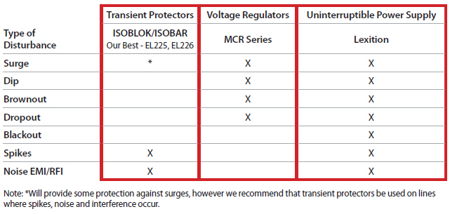
Once the problem has been defined, the solution can be implemented. Surges can be blocked by a simple inductive filter or a clamping device such as an avalanche diode. These devices are sometimes found as built into an outlet strip and sometimes use a Metal Oxide Varistor or MOV. Although an MOV can be effective for a while, it does degrade over time, and after a few surge events can be rendered completely ineffective with no indication that it is no longer providing protection. Using a more complete surge suppressor system provides a much more effective solution. Sags can only be overcome by a device that can boost the power to the recommended level. This requires a more sophisticated system that provides voltage regulation such as the Sola MCR series. Transients can be the most dangerous type of power disturbance to electronic circuits. The suppression of transients can vary from a simple combination of devices mentioned above, to a multiple stage active filtering and suppression circuit as in the EL226 AC Transient Protector.
One of the key features to be aware of in any transient suppression application is the response time. Transients are defined as being less than half of a cycle (1/30 of a second in terms of USA electrical supplies) but they can be as short as a few nanoseconds (billionths of a second)! In fact, the shorter the transient, the more likely it is to simply pass right through most power supplies and enter directly into the circuitry where it can cause not only destructive damage to the components, but also masquerade as a logic spike, causing damage to microprocessors.
That could result in intermittent and hard-to-diagnose problems later on. A few of the specifications to look for in a Transient Voltage Suppression Solution (TVSS) include: surge rating, response or clamping time, maximum continuous over voltage (MCOV), and let-through voltage (LTV). Surge Rating: the peak surge current per mode, by phase and/or total, which a TVSS can handle without failure. Surge ratings are usually given in joules. A joule is a measurement of energy. Energy is a measurement of power over time. A joule is equal to 1 Newton-meter, or 1 watt-second. The more joules, the higher a surge the TVSS can withstand. A rating of 400 or more joules is a good rating for a TVSS.
Response Time: the time it takes a TVSS to react to a transient activity and clamp to protect equipment. Response times are measured in nanoseconds or billionths of a second (10-9 or 0.00000001 seconds). The shorter the response time, the better the TVSS. A rating of less than 5 nanoseconds is good. MCOV: the term for the maximum continuous over voltage that a device can withstand. The higher the rating, the better. This value should be a minimum of 15 percent more than the rated voltage of the equipment to be protected, or in the case of a 120VAC TVSS, 138 volts or more. Let-through voltage: a measure of the device’s ability to protect downstream equipment. This value requires an explanation about AC power and sine waves.
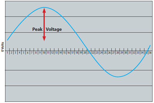
The AC power in most 120VAC systems consists of a sine wave as shown in figure 1.
Notice that the peak voltage is about 170 volts. 1.414 x 120 = 170. It is called a 120 volt supply because 120 volts is the RMS (root mean squared) value of the sine wave1. This is approximately equal to the average power. So, a let-through voltage of less than 170 volts would mean the TVSS would short out 60 times per second and fail very quickly. UL ratings do not allow a let-through voltage (LTV) rating of less than 330 volts. The higher the LTV is over 330 volts, the less protection the TVSS is providing.