


Grounding 101
The idea of grounding is that the earth itself acts as the electrical ground, providing not only a common reference for all electrical devices, but also a standard between devices regardless of location. The earth is used as the common reference conductor.
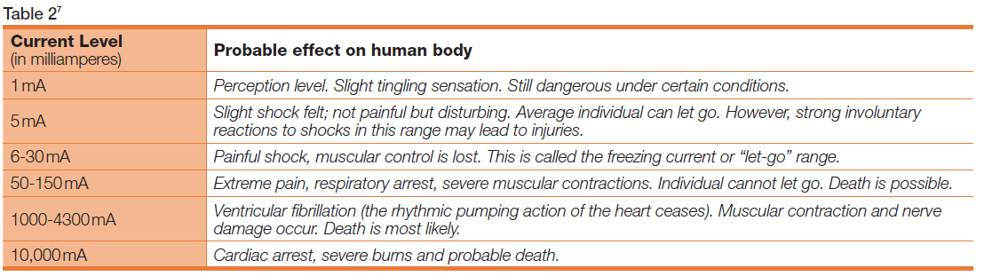
The consideration that the earth acts as a constant conductor is the underlying principle, and in the larger sense, it does. However, the connection to the ground or “earthing” needs to have the lowest resistance possible. Any resistance due to improper or faulty connections will allow the presence of a current to flow. In the context of safety, current flowing through a vital organ is what causes injury or death. The frequency of the alternating current, the duration of contact, and the path of contact are all important factors in determining the severity of the shock.
The connection to the earth consists of two basic parts: the grounding electrode and the connection (or bonding) to that electrode. Any resistance introduced in the grounding path could lead to a damaging or dangerous condition.
The relationship between resistance, current, and voltage is revealed in Ohm’s Law1:
I = V / R
Where :
I = current flow
V = voltage
R = resistance2
Using this equation, if the resistance is 0, then the current flow will be maximized in the ground circuit. (This is what you want, not current flow in another path that does not include the ground, but may include YOU!)
The accepted National Electrical Code (NEC), standard for a grounding circuit is 25 ohms or less, but much lower values can be obtained using multiple grounding electrodes.
“A single electrode consisting of a rod, pipe, or plate that does not have a resistance to ground of 25 ohms or less shall be augmented by one additional electrode of any of the types specified by 250.52(A)(2) through (A)(7). Where multiple rod, pipe, or plate electrodes are installed to meet the requirements of this section, they shall not be less than 1.8m (6ft) apart”. - Section 250.56 of the National Electrical Code.
Recently the following was added:
“In facilities with sensitive equipment it should be 5.0 ohms or less.”3
The Grounding Electrode
The usual form of grounding an electrode is a copper rod, sunk into the earth at a point near the device or electrical service to be protected. NEC calls for a minimum of 8 feet of electrode to be in contact with the earth. However, not all “earth” has the same electrical properties. (See Table 1).
To overcome this variable, sometimes multiple numbers of rods can be placed in an area to lower the resistance to ground.
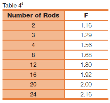
When using multiple ground rods, they are all connected in a “daisy chain” and one conductor is used to connect to the service or device to be grounded. This effectively places them in parallel and the resulting resistance is lower. Although it would seem the resistance is in direct proportion to the number of rods, the calculation is a little more complicated.
The total resistance of a multiple rod system is calculated by using the formula:
Rt = (Rs/n) ´ F
Where:
Rt = combined ground resistance of the system
N = number of electrodes
Rs = typical resistance of one electrode
F = factor shown in table 4 for the number of rods
Testing for earth ground resistivity requires the use of an earth ground resistivity meter and some additional stakes and cabling to measure the resistance between the grounding conductor and earth. One of the most accepted tests uses the Wenner method developed by Dr. Frank Wenner of the U.S. Bureau of Standards (now known as NIST) in 1915.6