Is the website displaying in the correct language? Please confirm or select a different language.
Your region has been set automatically. Please confirm or select a different region.
The Basics of Load Cell Wiring and Trimming
Learn the basics of load cell wiring to better understand your weighing system and recognize wear before it causes errors that require a trained technician.
Load Cell Wiring Basics
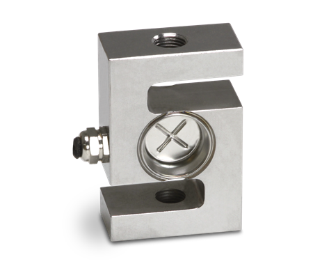
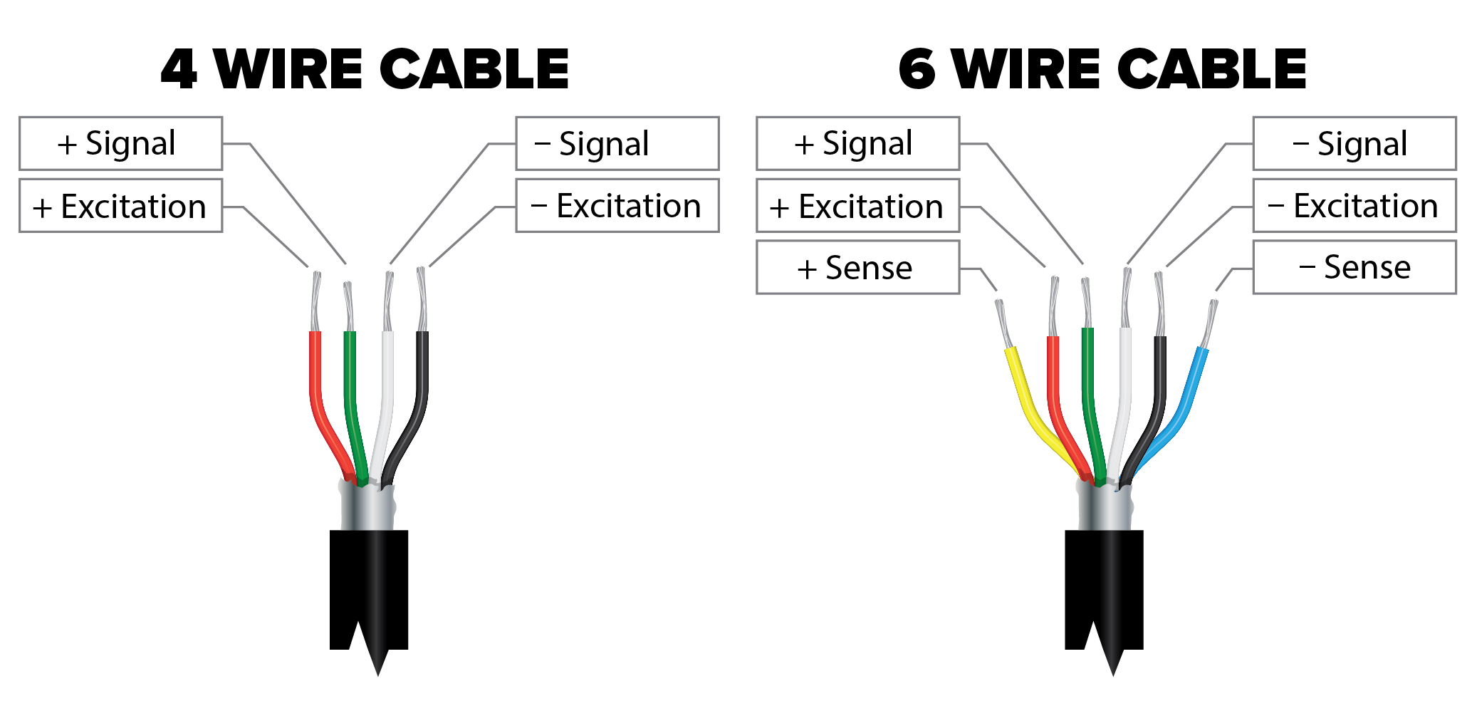
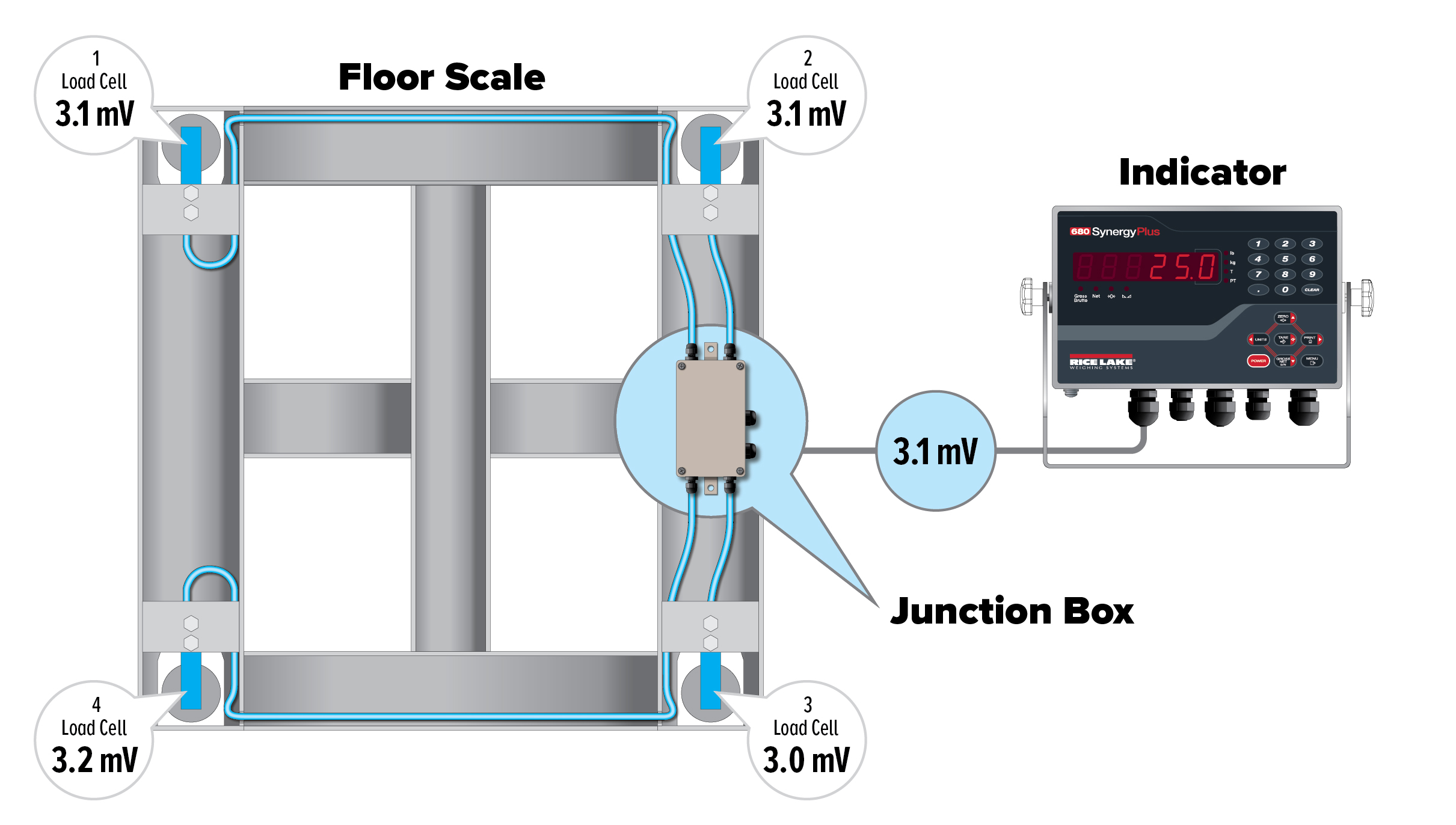
Load cells can have four or six wires. Both versions have positive and negative signal and excitation lines. The six-wire load cell also has positive and negative sense lines. Sense lines are linked to the sense connections of the system’s indicator, sometimes through a junction box, allowing the indicator to know a load cell’s actual voltage.
The sense lines continuously send information to the indicators, so if there is a voltage drop between the indicator and load cell, the indicator automatically adjusts the voltage. This compensates for the loss of voltage or amplifies the return signal to compensate for reduced power to the load cell.
Load cell wires are color-coded to ensure proper connections. Each brand uses its own color codes, so technicians need manufacturer-provided wiring color guides. Some manufacturers, including Rice Lake Weighing Systems, offer online wiring guides to assist technicians.
What Is Load Cell Trimming
Load cell trimming, or load cell summing, involves tying load cell output signals together. This happens in a junction box, which sends the summed signal to the indicator. It’s necessary to trim load cells when the weight distribution to each load cell isn’t equal. Trimming ensures the scale weighs correctly regardless of where the load is applied to the scale.
For example, in vessel loading processes, the presence of agitators or materials such as powder can affect how material and weight are distributed to each load cell.
Load cell manufacturing processes also permit some variation between load cells, which can cause load cell outputs to vary and result in inaccurate measurements. If trimming isn’t done, accuracy may be off due to the slight variations from manufacturing.
Steps for Load Cell Trimming
There are two different types of load cell trimming that scale technicians rely on when installing multicell weighing systems.
Excitation trimming
Excitation trimming is the oldest method of trimming load cell output signals. Excitation trimming adds resistance to the excitation circuit while reducing excitation voltage at the load cell.
The system’s load cell with the lowest output receives full excitation voltage, while other load cells receive proportionately smaller excitation voltages. This creates matched outputs for all load cells. To test in the field, do the following:
- Check individual cell ratings
- Inspect wiring
- Use a test weight on each load cell
- Adjust cells to the lowest cell reading
- Test weight and confirm new accuracy
Signal trimming
Signal trimming is the most common and popular type of trimming. It’s compatible with nearly all indicators and is typically unaffected by temperature changes or excessive system vibrations.
Signal trimming involves adding a relatively high parallel resistance between the signal of each load cell, which creates a leakage path that diverts some of the available load cell signal away from the indicator. When parallel resistance increases, more load cell signals are available. To perform signal trimming in the field, follow these steps:
- Set jumpers for potentiometers and disable unused load cells
- Use a test weight on each load cell
- Adjust potentiometers to the lowest load cell’s reading
- Test weigh and confirm new accuracy
Rice Lake Weighing Systems Load Cell Resources
Load cells can seem complicated, but Rice Lake offers resources to make maintenance and installation simple. Rice Lake’s load cell and weigh module resource center provides additional articles, videos and more on these weighing components.